Building Refinement Assets - Conceptual Data Model (CDM)
Building the Conceptual Data Model (CDM)
Purpose
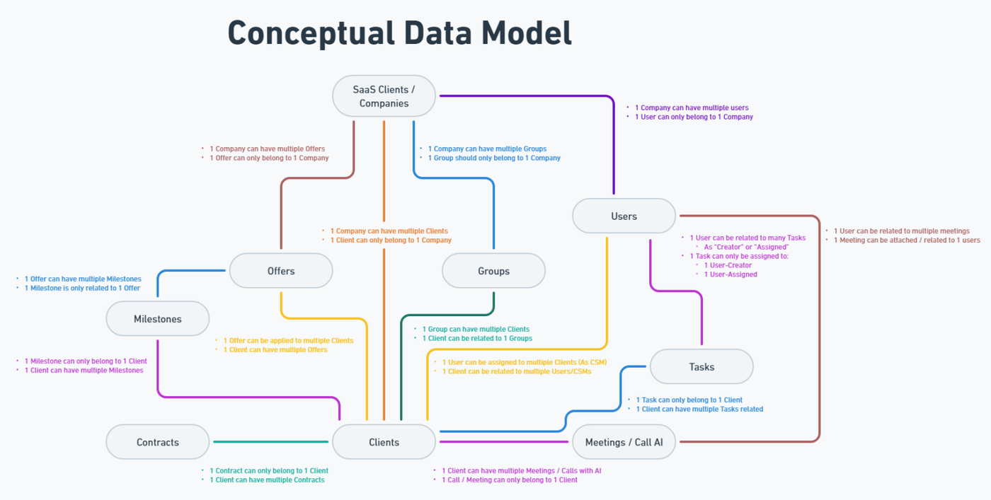
The Conceptual Data Model (CDM) is a visual representation of the core entities the platform will manage, along with the relationships between them. It provides a high-level structural overview of the system, allowing all stakeholders to understand what data objects exist and how they are connected.
Objective
The CDM must clearly answer:
-
WHAT are the key entities or objects the platform will handle?
-
HOW are these entities connected or related?
-
What is the parent : child structure between entities?
📌 Example: A User is the parent of many Requests; a Company may be the parent of many Users or Projects.
This structure helps define ownership, data hierarchy, and supports navigation, filtering, and permissions logic.
Step-by-Step Procedure
🔹 1. Identify Entities
-
Review previously confirmed assets (especially the Process Flow and User Flows) to extract a complete list of distinct objects or record types that the system must manage.
-
Each entity should represent a standalone data concept, such as:
-
User, Request, Task, Shipment, Product, Comment, Invoice, Message, Company.
-
🎯 These are the building blocks of the database, interface, and app logic.
🔹 2. Define Relationships
-
Analyze how entities are linked or nested based on process logic:
-
One-to-One (1:1)
-
One-to-Many (1:N)
-
Many-to-Many (N:N) – only if clearly required
-
-
Focus on identifying parent : child relationships, which will define:
-
Ownership and visibility rules
-
Record grouping (e.g., All Tasks under a Project)
-
🔹 3. Build the Diagram
-
Create a visual diagram using Whimsical, inside the same Project Scope Document for the corresponding project.
-
Each entity should be represented as a single box with only the entity name (do not include fields).
-
Use directional connectors or labeled lines to indicate relationship types (1:1, 1:N, N:N).
- 1:1 - One to One relation (One User can only have one assigned Vehicle; One Vehicle can only be assigned to one User)
- 1:N - One to Many relation (One User can have multiple assigned Vehicles; One Vehicle can only be assigned to one User)
- N:N - Many to Many relation (One User can have multiple assigned Vehicles; One Vehicle can be assigned to multiple Users)
-
Ensure visual clarity — avoid unnecessary complexity or crossovers.
🔹 4. Clarify Scope of Detail
-
At this stage there is no need to include field-level details inside entities at this stage.
-
Field definitions can be explored in the Forms & Fields tab of the Datasheet; Full Data Model will be developed later by the Dev Team.
📌 The CDM is a strategic asset, not a technical schema.
🔹 5. Finalize & Reference
-
Validate that all major entities and relationships in the CDM are reflected in:
-
The Forms & Fields tab
-
The User Flows
-
The Permissions Matrix (who interacts with what)
-
-
Once complete, upload or link the diagram in the corresponding Plutio scope task for internal visibility.
✅ No formal client approval is required for the CDM, but it must remain aligned with the rest of the confirmed scope.
Deliverable
A finalized Entity–Relationship Diagram created in Whimsical, showing all relevant entities and their relationships (including parent–child hierarchy).
📌 Optional Extension: External Data Source Mapping
For projects that require ongoing data import from external platforms, the BA is responsible for defining and documenting the integration logic at a conceptual level.
This includes:
-
Identifying the external source (e.g. CRM, ERP).
-
Locating the correct table or endpoint containing the required data.
-
Validating API access — API documentation is often outdated or incomplete, so it’s important to test endpoints directly (with Dev support if needed) to ensure they behave as expected.
-
Mapping source to target fields, including:
-
Source table and field
-
Target table and field in the new platform
-
Any filters or conditions (e.g., only import records with "Status" = "Open")
-
Expected sync frequency (e.g., daily at 8:00 AM EST, weekly, user-triggered)
-
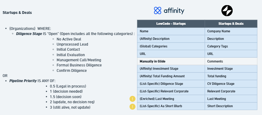
The final deliverable is a visual mapping table showing side-by-side field alignment between the external source and the platform, including logic notes (e.g., ⚠️ conditional filters, manual steps).
📌 This mapping serves as a reference for development and should be saved alongside the CDM diagram or linked within the Scope Document.
Deliverable